Wire screens
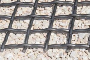
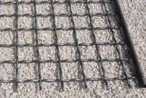
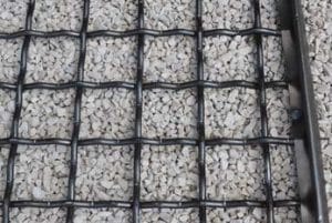
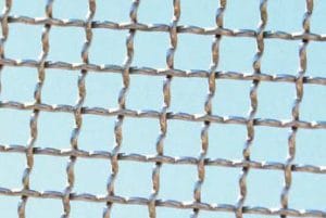
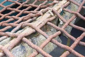
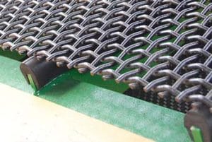
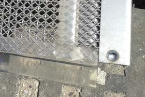
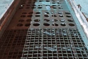
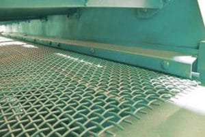
Geha Laverman provides different types of wire screens for cost effective screening and sorting of, products such as, sand, gravel and debris.
The screen decks are made of spring steel wire according to DIN 17223, Class A and stainless and acid-
resistant wire according to DIN 1.4301/1.4310.
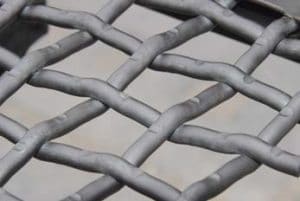
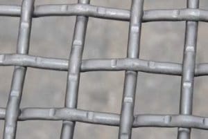
Other materials are also possible. We can offer – heavy duty, Extra heavy duty, standard woven mesh panels, self-cleaning mesh, piano wires, elongated mesh panels. Various configurations and sizes available, traditionally braided, bent, stamp- or press-welded into mesh sizes from 0.5 to 185 mm and wire thicknesses of 0.22 to 20 mm.
Available for many brands and types of machines in accordance with original dimensions.
Screening Process
Screening is a process described as a mechanical distribution of material particles based on their size and their acceptance or rejection by the screen surface of the screens installed on the decks of the screening machine. In other words, it is a classification of materials by size.
Screening is a process defi ned as a mechanical division of material particles on
the basis of their size and their acceptance or rejection done by the screening surface
of the screens installed on the decks of the screening machine. In other words it’s a
classification materials by size.
Material discharged to a screening decks will fl ow along their surface due to vibration
transmitted to the screenbox (machine box with one or more screening decks)
via eccentric shaft or vibration motor. This vibration is called an Amplitude and is
measured from the top to bottom of its stroke.
The force created by this amplitude needs to be sufficient to run the flow of feed material over the screening surface and to knock out particles caught in the screen openings but unable to pass through.
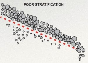
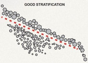
Force value is determined by the particles volume, mass, screening surface slope and particle tendency to peg.
Stratification occurs as result of vibration and makes coarse material to rise and fine material to fl ow through the screening surface.
Excessive vibration increases the ability of the machine deck to move the particles along its surface and defeats their tendency to peg, but on the other hand decreases stratification resulting in poor efficiency.
Efficiency is defined as a percentage of undersized particles in the feed material
which has actually passed through an opening area of the screening deck.
Choosing the right type of the screen is one of the most important factors providing the most satisfying screening results. Geha Laverman delivers wide range of professional meshes as well as the equipment for their proper installation.
Woven wire meshes - square
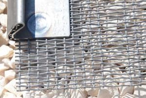
Basic woven wire mesh with square opening and plain wave.
USAGE
For screening fine and medium materials where high cubicity is expected.
CHARACTERISTICS
► openings precision
► high granulometric accuracy
► high wear resistance
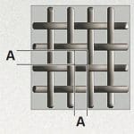
OPENING DETAILS
opening width and length - A
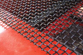
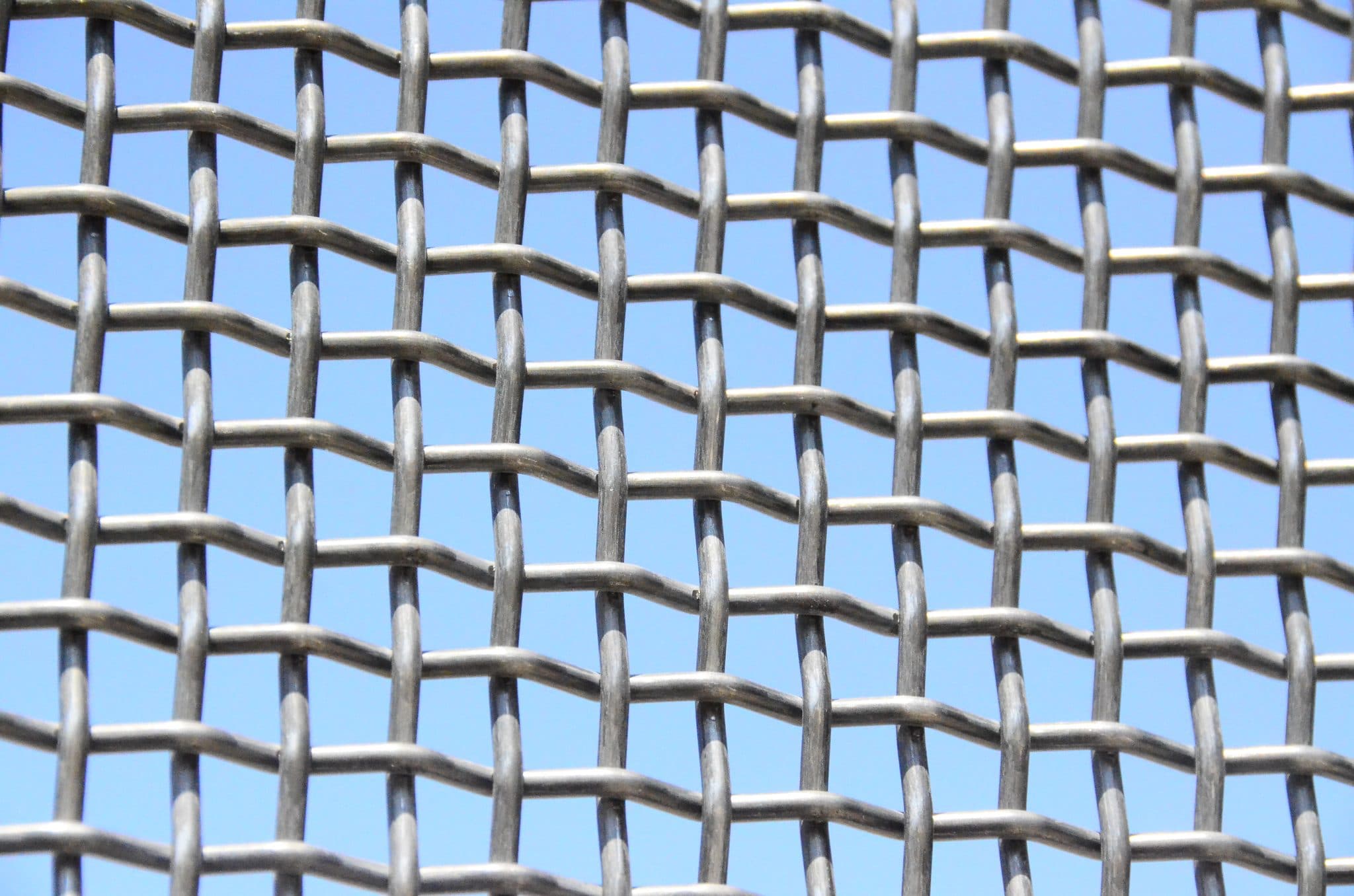
Woven wire meshes - rectangular
USAGE
For products with low amount of oblong particles or product with high amount of oversized material acceptable in the output.
CHARACTERISTICS
► maximization of cubic products sieving
► larger opening area
► increased capacity
► moist products screening
► removing fines
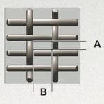
OPENING DETAILS
A - opening width
B - opening length
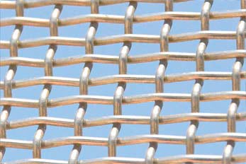
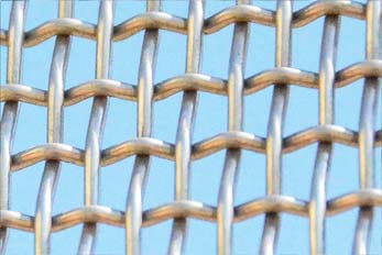
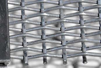
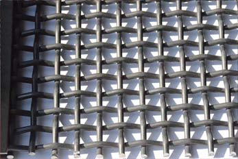
Woven wire meshes - LOCK CRIMP
Woven wire mesh with square or rectangular opening and lock-crimp wave.
USAGE
For screening medium and large materials where high efficiency and long lifetime is expected.
CHARACTERISTICS
► screening efficiency
► openings precision
► increased rigidity
► high granulometric accuracy
► high wear resistance

OPENING DETAILS
opening width and length - A
Woven wire meshes - INTERCRIMP
Woven wire mesh with square or rectangular opening, intercrimped wave and extra thin wires. Intercrimp is a variation of plain wave, where wire intersections occur at every third, fifth or seventh crimp of the wave.
USAGE
For sticky materials where higher capacity is expected and decreased operational life time
is
acceptable.
CHARACTERISTICS
► excellent screening efficiency
► openings precision
► increased rigidity
► high granulometric accuracy
► enhanced capacity
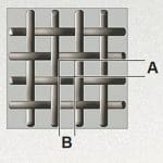
OPENING DETAILS
A - opening width
B - opening length
Welded wire meshes
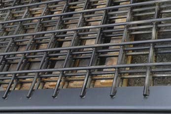
Welded plain wire grid with square or rectangular opening.
USAGE
For screening coarse, medium and thick materials, where long operational life time is expected.
CHARACTERISTICS
► superb opening rigidity
► high granulometric accuracy
increased life time
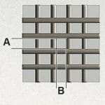
OPENING DETAILS
A - opening width
B - opening length
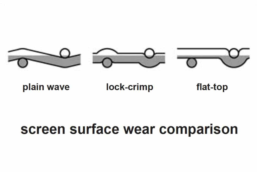
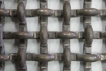
FLAT-TOP woven wire meshes
Woven wire grid with square or rectangular opening, fl at-top wave, smooth top surface and extra solid structure.
CHARACTERISTICS
► flat top surface providing even wear
► increased opening rigidity
► high granulometric accuracy
increased life time
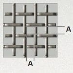
OPENING DETAILS
A - opening width
and length
Slotted opening woven wire meshes
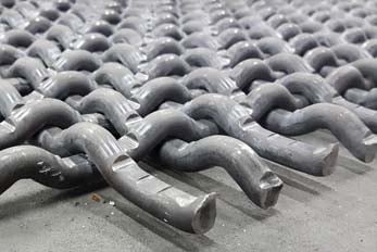
Woven wire mesh with slotted opening, multicrimped (longitudinal wires) and plain wave (crosswires). Much larger opening area than any other woven meshes. Slotted opening should be parallel to the tensioning direction and the feed direction if possible.
USAGE
Damp, hard to sieve, sticky materials where high amount of oblong product is acceptable in the
output.
CHARACTERISTICS
► excellent for natural cubic products sieving
► larger opening area
► increased capacity
► sieving of moist and sticky products
► removing fines
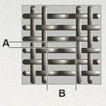
OPENING DETAILS
A - opening width
B - opening length
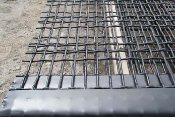
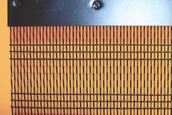
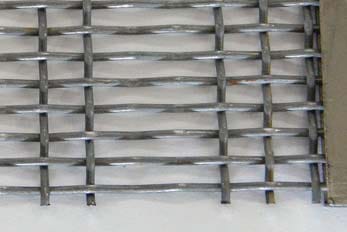
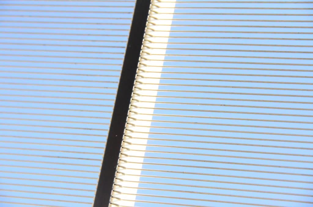
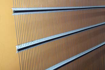
Piano wire screen mesh
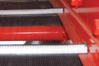
Plain wire self-cleaning mesh with moveable cross-strip bindings.
USAGE
For sticky, hard to sieve materials, where clogging occurs at the intersections of the wires in conventional screens, where high capacity is expected and decreased operational life time is
acceptable.
CHARACTERISTICS
► flat surface
► recommended for fouling products
► excellent capacity
► large opening area
OPENING DETAILS
A – opening width
Self-cleaning meshes
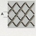
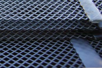
Woven wire self-cleaning mesh with longitudinal wires crimped within the panel surface, fl exible
polyurethane cross bindings for highly abrasive materials and diagonal aligned square opening.
Anti-clogging and anti-plugging effect is achieved by natural vibration and cutting effect of the wires, caused by the feed material beating on the screen surface.
USAGE
For sticky, hard to sieve materials, where clogging occurs at the intersections of the wires in conventional screens.
CHARACTERISTICS
► flat surface
► excellent capacity
increased life time
► high classification accuracy
OPENING DETAILS
opening diameter - A
wire diameter - Ø
Self-cleaning meshes with straight wire
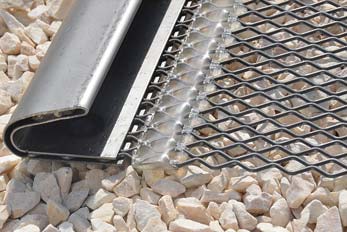
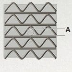
woven wire anti clogging mesh with alternately straight and crimped within the panel surface longitudinal wires, flexible polyurethane cross bindings for highly abrasive materials and triangle shaped opening. Anti-clogging and anti-plugging effect is achieved by natural vibration and cutting effect of the wires, caused by the feed material beating on the screen surface. This type of screen provides higher rigidity.
USAGE
for sticky, hard to sieve materials, where large size of the input material and small size of output is expected, or high level of impact occurs.
CHARACTERISTICS
► flat surface
► excellent classification accuracy
► designed for heavy/large and fouling input material
OPENING DETAILS
A - opening diameter
Ø - wire diameter

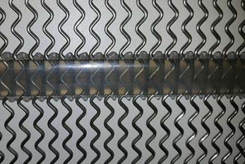
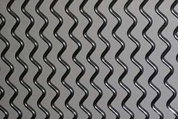
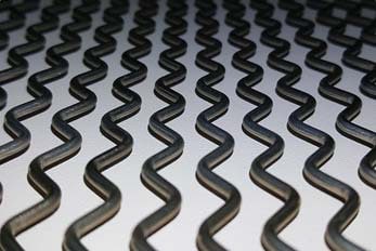
Self-cleaning meshes zig-zag
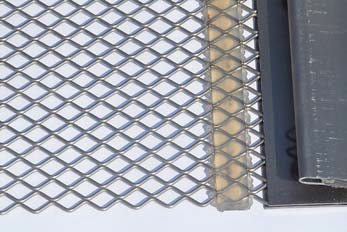
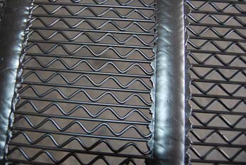
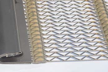
woven wire anti clogging mesh with longitudinal wires crimped within the panel surface, flexible polyurethane cross bindings for highly abrasive materials. Anti clogging effect is achieved by the absence of any contact between the warp wires and natural oscillation caused by the feed material beating on the screen surface.
USAGE
for sticky, hard to sieve, moist materials.
CHARACTERISTICS
► flat surface
► designed for small or sticky materials
► large opening area
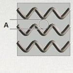
OPENING DETAILS
opening diameter - A
wire diameter - Ø
Punch plates
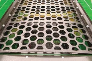
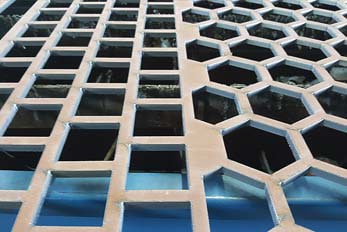
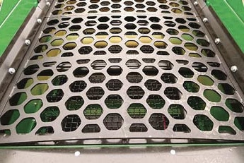
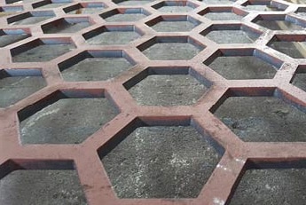
Punch plates are screens designed for heavy duty screening, where high impact and wear resistance is needed.
There are numerous apertures patterns available such as round, square, hexagonal,
slotted etc. Punch plates are ideal for screening large size feed materials.
USAGE
For highly abrasive materials, where large size of the input material and high level of impact
occurs.
CHARACTERISTICS
► flat surface
► excellent classification accuracy
► designed for heavy/large and/or abrasive input material
► highly customizable apertures shapes and opening area
Opening area details
Opening area is the percentage of the area of all openings in the total screen surface. The thinner the wire, the larger
opening area and more efficient screening process. Wire diameter selection determines many different screening factors (see table
below).
| Screening Efficiency | Material Flow | Opening area | Opening Count | Wear Resistance | Opening Rigidity | |
|---|---|---|---|---|---|---|
| Thicker Wire | Lower | Decreased | Smaller | Lower | Higher | Higher |
| Thinner Wire | Higher | Increased | Larger | Higher | Lower | Lower |
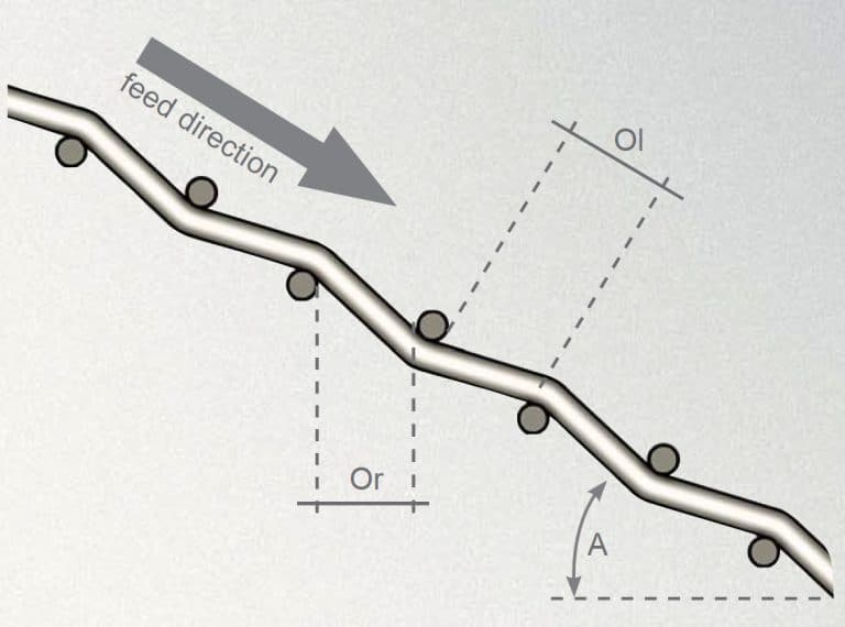
Effective opening size in every screen type with cross wires mounted on the incline
deck is slightly different than mesh opening size.
Screenbox deck inclination angle affects the separation size in the following way:
Or = Ol x cosA
where:
Ol - opening length
Or - separation size / effective opening length
A - screenbox deck inclination angle
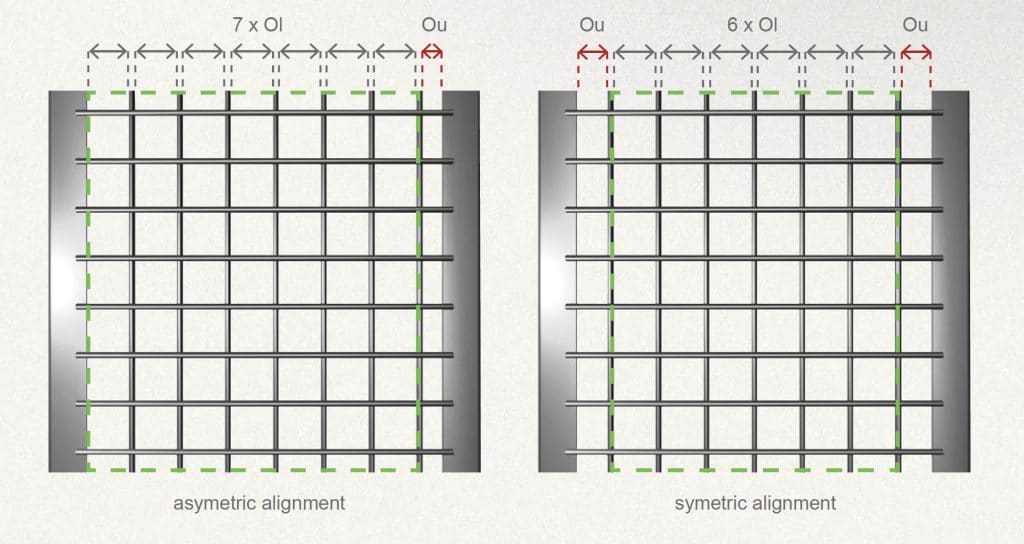
Openings alignment is another important indicator of how large is the appropriate opening area. Symmetry isn’t always desirable
factor in that matter. For example (see pictures below), forced symmetry of apertures alignment in the screen results in smaller
effective separation area and decreased screening efficiency than in the screen with asymmetric alignment.
The larger aperture size, the bigger difference in effective screening.
Pegging and blinding
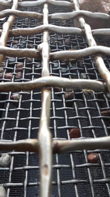
Pegging of screen meshes is the unwanted situation, where feed material particles get stuck in the mesh aperture in the way, that their 2/3rd of mass is present below the screen surface.
There can be several indicators of this issue such as:
- Under-loaded screen
- Over-loaded screen with poor stratification
- Too large amplitude which may lower screening efficiency and decrease stratification
- Reducing pegging can be achieved by reversing vibrator flow from contra flow
- Incorrect (too large) wire diameter for certain shape type of feed material
- Too small opening area, or wrong type of aperture size
(consider slotted opening mesh) - Excessive water jet pressure at the inflow end can cause a large quantity of fine particles to be sieved and lower amount of these on the discharge end, causing lack of stratification in the area and peggin of screen apertures.
BLINDING
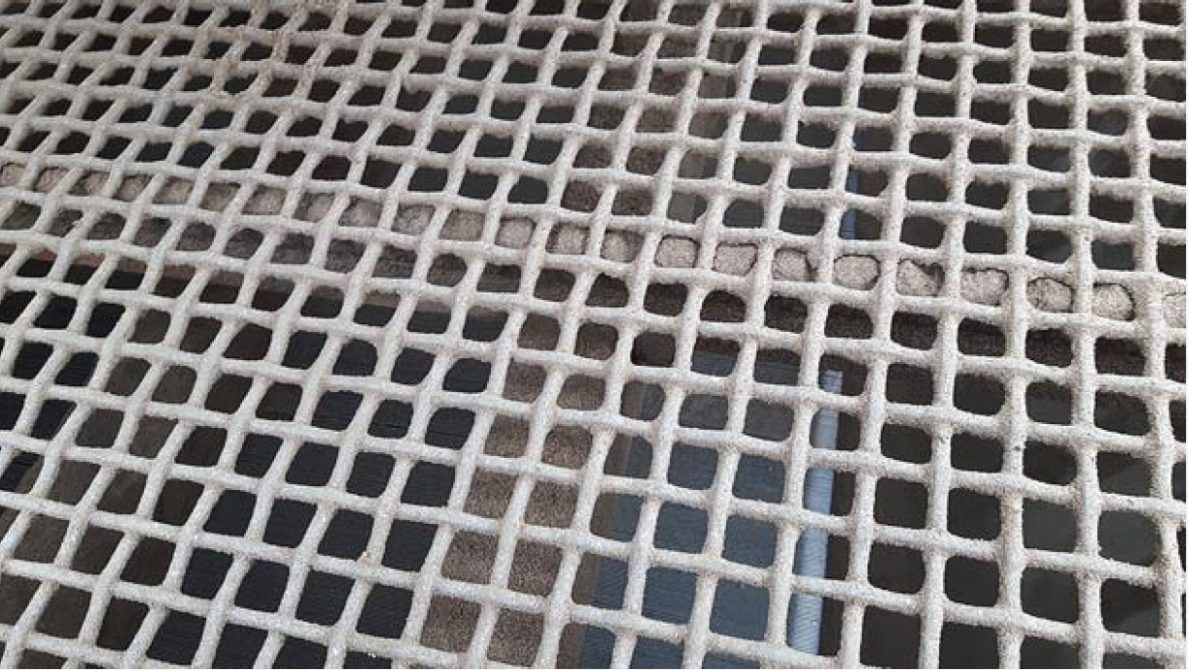
Blinding of apertures is another undesirable process when screening media contains fi ne, damp and sticky material.
When fines, minerals and other components adhere and go through the openings, they create a thick paste which clogs up the mesh openings.
Fine material particles adheres to the coarse material particles providing poor screening efficiency. Blinding also affects the wire
diameter of the mesh resulting in decreased screening accuracy and stratification.
There are several solutions to overcome blinding:
- Increase opening area by using slot
openings
instead of square ones - Use stainless wire meshes
- Decrease screen wire diameter
- Use self-cleaning meshes
- Use heated screens
Tensioned dimensions
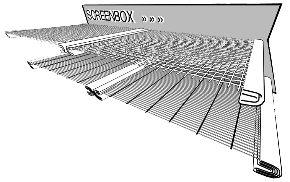
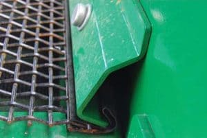
Proper screen end tension is crucial for mesh wear life and machine life. Wrong end tension can result with screen damage and incorrect screening process in many aspects. Most often this kind of screen mounting solution is used on the bottom decks of
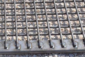
the screenbox. Screens are specially designed with end tensioning hooks types, and proper tension is achieved with lightly curved
tensioning bars, also called “banana” bars. Convex side of the tensioning bar must fi t into hook concave, and its curve have to be
mounted face towards the center of hook inward curve. Tensioning is achieved with screen tensioners mounted on each side of the tensioning bar. Proper tension is attained by straightening tensioning bar, done by adjusting the end tensioners.
Tensioning instructions:
- Check the support bars and make sure they’re straight and evenly covered with cushion rubber.
- Remove material leftovers from the support ledges.
- Check you have the correct hook type, opening and screen dimensions.
- Ensure that fi xed end is straight and fi rm, and tensioning bar is properly curved and solid.
- Mount one screen hook on the fixed end, and slide tensioning bar into position at other end and secure it.
- Tension each side equally.
- Use a rubber hammer and bounce the sides of the mesh and compare it with its centre.
With properly tensioned screen, bouncing “feel” should be equal. - Mesh will stretch to some level within first few hours of screening, especially smaller openings.
Tensioning should be re-checked every few hours within first two days. - Tension and screen condition should be checked at the beginning of every shift.
- Replace cushion rubber if it gets damaged, never use two different cushion rubbers at the same support bar.

Side tensioning measurements
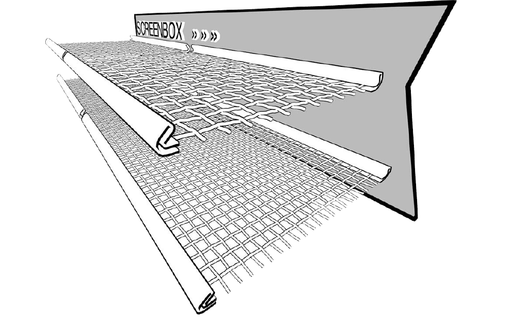
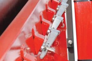
The screen hooks are mounted parallel to the material fl ow direction. Screens with thicker wires should be mounted at the
feed end of the deck. Decks are divided into sections, which gives the advantage of replacing only damaged or worn screen at a time,
saving installation time and product costs. Easy access to tensioning clamps mounted on both sides of the screenbox provides quick
and easy retensioning. Clamps have additional, wear protection function
Tensioning instructions:
- Check the support bars and make sure they’re straight and evenly covered with cushion rubber.
- Remove material leftovers from the support ledges.
- Check you have the correct hook type, opening and screen dimensions.
- Check that the screen width (hooks side) is equal to the clamping bar length
- Ensure that clamping bars are straight and solid.
- Mount the screen leaving equal clearance on both sides of the screenbox.
- Mount clamping bars into hooks conecaves, ensuring that they cover whole surface of the hook length.
- Install tensioning bolts, starting from the centre of the screen and tighten simultaneously, leaving equal clearance on both sides.
clearance on both sides - Check all tensioning bolts after one hour of screening.

End tensioning hooks chart
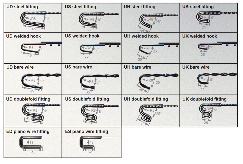
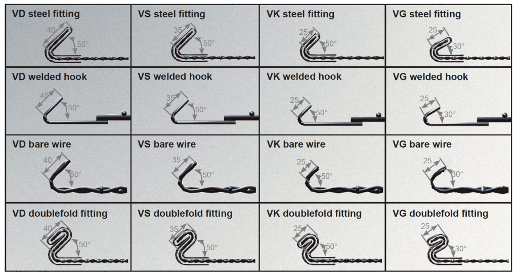
Vibrating deck screens are manufactured with several types of tensioning hooks. Proper screen tension determines
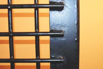
separation efficiency and wear life of the sieves. Depending on the screen wire diameter, bare wire hooks, weld on hooks,
hooks with steel fittings single or double folded are distinguished to fi t the deck correctly and optimize screen life time.
Hook fittings materials include carbon or stainless steel depending on environmental conditions and type of screening material.
hooks with steel fittings - hooks reinforced with steel plate provided as standard on screens up to 12mm wire diameter.
hooks with double folded steel fittings - additional hook reinforcement preventing pull-out on fine mesh screens.
ed hooks - welded bent plate for the screens with 5.5mm and larger wire diameters.
bare wire hooks - economical solution for the screens with 5.5mm and larger wire diameters.
Standard haken
Special hooks

Side tensioning hooks chart
Special hooks

Zs type hooks measurements
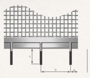
ZS type fl at tensioning hook with tensioning bolts is determined by several data such as number of bolts, bolt thread (from M12 to M16), bolt width (c), bolts spacing(a), measurement from screen edge to center of bolt (a).
Screen hooks are available to fit variety of different types of machines as well as specific custom designs such as wide range of weld on steel profiles, 90 degree bent fittings etc.
Cushion rubber
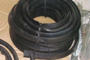
Cushion rubbers are absolutely essential to provide maximum wear life of the screens and machine life. It’s very important to replace every worn or damaged cushion rubber immediately, covering the whole length of the support bar. You should never use two different cushion rubbers at the same support bar at a time.
Cushion rubber, also called capping rubber protects the deck support bars from damage, and screens from cracking. The only exception of using cushion bars are the piano wire screens, which have their own moveable strips (round or square) mounted directly on bare support bars.
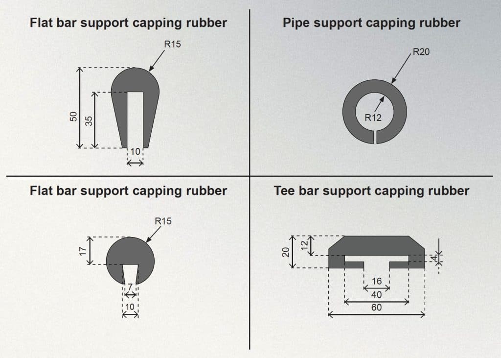
Screen edge finishing
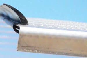
Some screens and/or screen mounting solutions demand specific screen edge finishing to provide proper sieving conditions. End tensioned screens with small wire diameters and apertures need additional
edge rubber sealings to prevent passing oversized material through the clearence between screen edges and the screenbox sides.
Side tensioned screens with finer apertures and wire diameters mounted on decks
with multiple sections should have additional overlaps or PU sealings (in some self cleaning screens) to over
overcome similar issue. It is considered that screens with wire diameters up to 1.5mm need one of the solutions mentioned above.
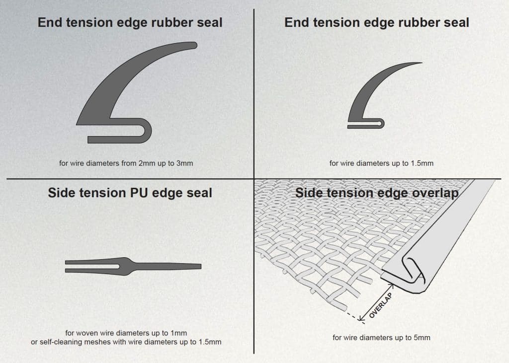
Joining side tensioned screens
For screenbox decks divided into sections with side tensioning systems, there is special screen joining
procedure for the screens with 5mm wire diameter or finer, where edge overlap is needed in every screen mounted on deck, except for the first one (impact screen) at the machine feed end. Minimum overlap length is 20mm and it depends on screen aperture and wire diameter.
For proper installation of the screen, hooked edged should be the same length as the clamping bars, and installation should begin from the lowest screen, at the discharge end of the deck, with overlap facing against the material flow direction.
Every next screen must be mounted above the previous screen overlap, to prevent material passing
between deck sections.
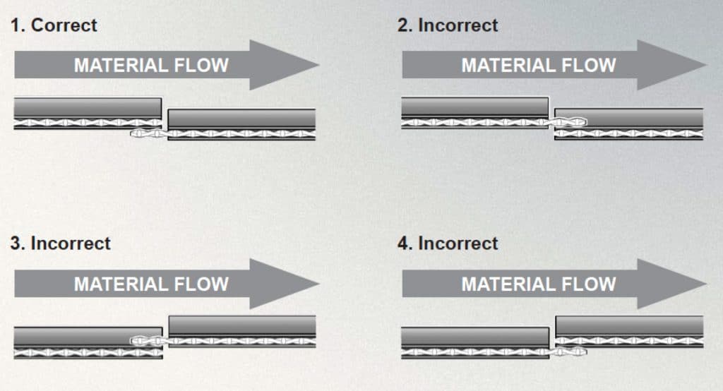
Options 3 and 4 are highly incorrect, because screening material can pass between two screen sections decreasing screening accuracy. Second option seems to solve this problem, but it’s still incorrect solution, cause fl owing material has its impact on the crosswires of the screen overlap, resulting in knocking them out of the screen, creating potential dangerous situation and damaging the screen.
Accesoires
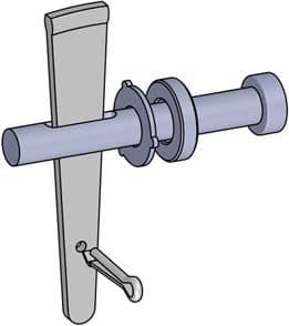
wedgetype bolts
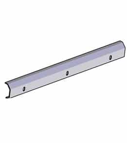
Clamping bars
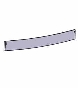
Tensioning bars
Openings and wires chart
Woven wire meshes
| Opening | Wire diameter |
|---|---|
| 1.5 | 1 |
| 1.6 | 1.2, 1.3 |
| 1.8 | 1.2 |
| 2 | 1.2, 1.5 |
| 2.2 | 1.2 |
| 2.3 | 1.2, 1,5 |
| 2.5 | 1.2, 1,5 |
| 2.6 | 1.5 |
| 2.7 | 1.2 |
| 2.8 | 1.5 |
| 3 | 1.2, 1.3, 1.4, 1.5 |
| 3.1 | 1.5 |
| 3.2 | 1.2, 1.5 |
| 3.3 | 1.2, 1.5 |
| 3.4 | 1.2 |
| 3.5 | 1.5 |
| 3.6 | 1.8 |
| 3.7 | 1.5 |
| 3.8 | 1.2, 1.5, 1.8 |
| 4 | 1.5, 1.8, 2 |
| 4.5 | 1.5, 2, 2.5 |
| 4.7 | 1.8 |
| 4.8 | 1.8 |
| 5 | 1.5, 2, 2.5 |
| 5.5 | 2, 2.5 |
| 5.8 | 1.5 |
| 6 | 1.5, 2, 2.5, 3 |
| 6.3 | 3 |
| 6.5 | 2.5 |
| 7 | 2, 2.5, 3 |
| Opening | Wire diameter |
|---|---|
| 7.5 | 1 |
| 8 | 1.5, 1.8, 2.5, 3 |
| 8.5 | 3 |
| 9 | 2.5, 3, 3.5 |
| 9.5 | 2.5, 3, 3.5 |
| 10 | 1.2, 1.5, 1.8, 2.5, 3, 4 |
| 10.5 | 3.5 |
| 11 | 2.4 |
| 11.5 | 2.5, 3.5, 4 |
| 11.9 | 2 |
| 12 | 3 4 |
| 12.5 | 2.5, 4 |
| 13 | 3, 4, 5 |
| 13.5 | 4, 4.5 |
| 14 | 4, 4.5, 5, 5.5 |
| 14.3 | 2.5 |
| 14.5 | 4, 4.5, 5, 6 |
| 15 | 2, 3, 4, 4.5 |
| 15.5 | 4, 4.5, 5 |
| 16 | 2, 4, 5 |
| 16.5 | 4, 4.5 |
| 17 | 5, 6 |
| 17.5 | 4.5 |
| 18 | 4, 4.5, 5, 5.5 |
| 18.5 | 4.5, 5 |
| 19 | 4, 4.5, 5 |
| 19.5 | 5 |
| 20 | 2, 3, 4, 4.5, 5, 5.5, 6 |
| 20.5 | 5, 6 |
| 21 | 4, 5, 5.5 |
| Opening | Wire diameter |
|---|---|
| 21.5 | 5 |
| 22 | 5, 5.5, 6 |
| 23 | 3, 5.5 |
| 23.5 | 5.5 |
| 24 | 5, 5.5, 6, 7 |
| 25 | 3, 4, 4.5, 5, 5.5, 6 |
| 26 | 5.5, 6 |
| 27 | 5, 6, 7 |
| 27.5 | 4, 4.5 |
| 28 | 6.5 |
| 28.5 | 7 |
| 29 | 6, 10 |
| 30 | 4, 5, 5.5, 6, 6.5, 7, 10 |
| 31 | 6.5, 9 |
| 31.5 | 7, 8 |
| 32 | 5.5, 6.5, 7, 8 |
| 33 | 6.5, 8 |
| 33.5 | 8, 9, 10 |
| 34 | 7 |
| 34.5 | 6.5 |
| 35 | 7, 8, 10 |
| 36 | 7 |
| 37 | 7, 8 |
| 38 | 8 |
| 40 | 3, 4, 5, 6, 7, 8, 9, 10 |
| 42 | 8 |
| 43 | 10 |
| 45 | 5.5, 8, 10 |
| 47 | 8, 9 |
| 48 | 8 |
| Opening | Wire diameter |
|---|---|
| 49 | 10 |
| 50 | 8, 9, 10 |
| 52 | 10 |
| 53 | 9 |
| 55 | 8, 9, 10 |
| 56 | 9, 10 |
| 57 | 8, 9, 10 |
| 58 | 9 |
| 60 | 8, 9, 10, 12 |
| 63 | 9, 10, 12 |
| 65 | 9, 10, 12 |
| 67 | 9 |
| 68 | 10 |
| 70 | 8, 10, 12 |
| 75 | 10 |
| 80 | 8, 10, 12 |
| 83 | 8 |
| 85 | 10 |
| 87 | 12 |
| 90 | 10, 12 |
| 100 | 10, 12 |
| 103 | 10 |
| 110 | 10, 12 |
| 117 | 10 |
| 120 | 12 |
| 132 | 12 |
| 140 | 12 |
| 150 | 12 |
Piano wire screen mesh
| Opening | Wire diameter |
|---|---|
| 1.2 | 1 |
| 1.5 | 0.65, 0.85, 1.0 |
| 1.7 | 0.65, 0.85, 1.0 |
| 2 | 0.65, 0.85, 1.0 |
| 2.5 | 0.65, 0.85, 1.0, 1.2, 1.3 |
| 3 | 0.65, 0.85, 1.0, 1.2, 1.3 |
| 3.5 | 0.65, 0.85, 1.0, 1.2, 1.3 |
| 4 | 0.65, 0.85, 1.0, 1.2, 1.3, 1.5 |
| 5 | 0.85, 1.0, 1.2, 1.3, 1.5, 1.8 |
| 6 | 1.0, 1.2, 1.3, 1.5, 1.8, 2.0 |
| 7 | 1.0, 1.2, 1.3, 1.5, 1.8, 2.0 |
| Opening | Wire diameter |
|---|---|
| 8 | 1.0, 1.2, 1.3, 1.5, 1.8, 2.0 |
| 9 | 1.2, 1.3, 1.5, 1.8, 2.0 |
| 10 | 1.2, 1.3, 1.5, 1.8, 2.0 |
| 12 | 1.2, 1.3, 1.5, 1.8, 2.0 |
| 13 | 1.5, 1.8, 2.0 |
| 14 | 1.5, 1.8, 2.0 |
| 15 | 1.5, 1.8, 2.0 |
| 16 | 1.8, 2.0 |
| 18 | 1.8, 2.0 |
| 20 | 1.8, 2.0, 2.5 |
| 25 | 2, 2.5 |
Self-cleaning meshes
| Wire diameter | self-cleaning mesh openings | Self-cleaning mesh with straight wire openings | Self-cleaning zig-zag mesh openings |
|---|---|---|---|
| 1.2 | 1.5, 1.6, 1.8, 1.9, 2, 2.3, 2.4, 2.5 | 2.7, 2.8, 3, 3.1, 3.2, 3.5, 3.6, 3.7 | |
| 1.3 | 1.6, 1.7, 2, 2.2, 2.3, 2.4, 2.5, 2.6, 3, 3.15, 3.2, 4 | 2.9, 3, 3.3, 3.5, 3.6, 3.7, 3.8, 3.9, 4.3, 4.5, 5.3 | |
| 1.4 | 3, 3.15 | 4.4, 4.55 | |
| 1.5 | 4, 4.5, 5, 9 | 1.5, 1.6, 2, 2.3, 2.4, 2.5, 2.8, 3, 3.2, 3.5, 4, 4.5, 5, 5.5, 6, 6.3, 8, 9 | 3, 3.1, 3.5, 3.8, 3.9, 4, 4.3, 4.5, 4.7, 5, 5.5, 6, 6.5, 7, 7.5, 8.9, 9.5, 10.5 |
| 1.8 | 4, 4.5, 5, 5.7, 6, 6.2, 6.5, 7, 8 | 3, 3.2, 3.5, 4, 4.2, 4.5, 5, 5.2, 5.5, 6, 6.2, 7.2, 8, 10 | 4.8, 5, 5.3, 5.8, 6, 6.3, 6.8, 7, 7.3, 7.8, 8, 9, 9.8, 10.8 |
| 2 | 4, 4.5, 5, 5.7, 6, 6.5, 7, 8, 9, 10, 11 | 3.5, 4, 4.5, 5, 5.5, 6, 6.3, 6.5, 7, 8, 8.5, 9, 10, 11, 12 | 3.5, 4, 4.5, 5, 5.5, 6, 6.3, 6.5, 7, 8, 8.5, 9, 10, 11, 12 |
| 2.5 | 5, 5.5, 5.7, 6, 6.5, 7, 7.5, 8, 9, 9.5, 10, 11, 11.5, 12, 13 | 4.5, 5, 5.5, 6, 6.3, 7, 7.5, 8, 8.5, 9, 9.5, 10, 11, 11.5, 12, 14 | 7, 7.5, 8, 8.5, 8.8, 9.5, 10, 10.5, 11, 11.5, 12, 12.5, 13.5, 14, 14.5, 16.5 |
| 3 | 6, 6.5, 7, 8, 9, 9.5, 10, 11, 11.5, 12, 12.5, 13, 13.5, 14, 15, 16, 18 | 6, 7, 8, 8.5, 9, 10, 12, 12.5, 13, 14, 15, 18, 19, 20 | 9, 10, 11, 11.5, 12, 13, 15, 15.5, 16, 17, 18, 21, 22, 23 |
| 3.5 | 11.5, 12, 12.5, 13.5, 14, 15, 16, 20 | 8, 9.5, 13.5, 15, 16 | 11.5, 13, 17, 18.5, 19.5 |
| 4 | 12, 12.5, 15, 16, 17, 18, 19, 20, 22, 23, 24, 25, 26 | 15 | 19 |
| 4.5 | 16, 18, 20, 23, 24, 25 | 16, 18, 20, 23, 24, 25 | |
| 5 | 12, 16, 18, 20, 21, 22, 22.5, 23, 25, 27, 28, 30, 32, 35, 40 | ||
| 5.5 | 22, 25, 30, 32, 35, 40 |
Welded wire meshes
| Opening | Wire diameter |
|---|---|
| 20, 22, 25, 26, 30, 31, 32, 34, 35, 36,38, 40, 45, 50, 55, 60, 62, 63, 65, 70, 75, 80, 85, 90, 93, 95, 100, 105, 110, 115, 120, 125, 130, 140 ,150, 155, 170, 180, 200 | 10, 14, 16, 20 |
Flat-top woven wire meshes
| Opening | Wire diameter |
|---|---|
| 10 | 4 |
| 19.5 | 6.5 |
| 20 | 5.5, 6 |
| 24 | 4.5 |
| 25 | 6.5 |
| 30 | 7 |
| 31.5 | 5 |
| 35 | 8 |
| 40 | 9 |
| 50 | 10 |
| 55 | 10 |
| 60 | 10 |
